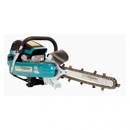
GeoRipper GR20 Chainsaw Trencher | Mini Trencher
MiniTrencher’s GeoRipper GR 20 includes a Makita® 8100 2-stroke engine (5.6 HP), 500 mm digging bar, two self-sharpening digging chains, 18mm combo wrench, spare nose bearing, spare drive belt and owners manual. The GeoRipper GR20 is a commercial, portable handheld trencher used for trenching electrical, irrigation, fiber optic, landscape edging, dog fencing, root barriers, etc.
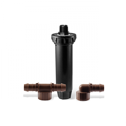
Rain Bird 1800 Spray to Drip Retrofit Kit
Rain Bird® 1800-RETRO is the easiest and fastest way to convert a conventional spray zone to a low-volume irrigation zone. The 1800 Retro internal assembly is easily installed into any existing 1804, 1806, or 1812 spray head bodies to retrofit existing system to Xerigation products.

Rain Bird HV Series Residential Irrigation Valves
These compact-designed plastic residential irrigation valves offer high performance and big savings. With a low price and easy maintenance, you can deliver the same quality and durability you expect from Rain Bird at an affordable price. HC Valves are designed with the benefit of over 5 decades of valve design experience.
Note: This test only works for water systems that are serviced by a municipal water service.
- Locate the outside faucet closest to the main line, or a utility sink and for best results you can install your irrigation plumbing tie in. (We will call this T “Tie-in”).
- Locate another faucet on your house and attach a pressure gauge (We will call this G “Gauge”).
- With faucet T completely open, check the pressure reading on the gauge at faucet G. If it is less than working pressure, turn down the water flow from faucet T until the reading reaches the working pressure your system requires (for example if you want to run your rotary heads at 35PSI and you will lose 12PSI in your plumbing and piping system you will require 47PSI at G). If it is greater than the working pressure, record the pressure reading and go to next step.
- Place a five-gallon bucket under faucet T and time how long it takes to fill it with water. This test tells you how much water available, measured in gallons per minute (GPM).
Double check your GPM using the following formula:
60 seconds / time to fill the bucket x 5 (bucket size) = _____ GPM
Enter your findings from the test here: ________ PSI ________ GPM
- This is how much water is available at the designated working pressure or at the higher reading that you recorded.
- Before you go any further, it is important to make sure you are starting off with the right flow and pressure information. You may be getting a higher flow then the hydraulic system of the house is designed to handle. Therefore taking a few minutes now may save you countless headaches later!
Now that you’ve recorded your home’s water capacity, let’s make sure your water meter and service line can handle it. Complete the next steps determine your actual system design capacity.
Flow Rates for Water Meters Meter Size Max. GPM 5/8” 10 3/4” 15 1” 25 |
- Water Meter Size
______ = ______ Max. GPM
Water meter size is stamped or printed on the face of the meter, or shown on your water bill
- Service Line Type/Size
_________ = ______ Max. GPM
- Type & Size
- Flow Rates for Service Lines and Sprinkler Lines
Maximum Recommended Flow | ||
Pipe Type | Pipe Size | Maximum GPM |
PVC (Plastic) |
|
|
Consider using 1″ Schedule 40 PVC pipe upstream of zone valves | 1″ Schedule 40 | 13 |
| 3/4″ Schedule 40 | 7.9 |
and at least 3/4″ Class 200 PVC (SDR21) pipe downstream of zone valves | 1″ Class 200 | 16.7 |
| 3/4″ Class 200 | 10.1 |
Galvanized | 3/4″ Galvanized Pipe | 8.3 |
| 1″ Galvanized Pipe | 13.5 |
Copper(Service Line) | 3/4″ Copper Tube | 6.8 |
| 1″ Copper Tube | 12.1 |
Polyethylene (Poly Pipe) |
|
|
In freezing areas poly pipe may be used downstream of zone valves | 3/4″ Poly Pipe | 8 |
1″ Poly Pipe | 13 | |
- Enter the Lower GPM From Steps 1 or 2
______Max. GPM (this is your design capacity)
- Example:
Water Meter Size | Service Line Type/Size |Enter the Lower GPM 1” = 25 GPM | 1” Schedule 40 PVC = 13 GPM 13 GPM = design capacity |
Note: It is recommended to use only 80% of the design capacity to allow for future household water consumption demand for domestic purposes
Foolproof Irrigation System Electrical Troubleshooting
To properly troubleshoot a 24VAC irrigation controller you must own a digital volt/ohm meter. Aquarius sells a very nice digital meter which can also be used for landscape lighting manufactured by Cast Lighting Item #CMETER.
With this tool you will use the VOLTAGE setting to test the controller output and the OHM setting to diagnose the field wiring. ALWAYS troubleshoot in this order: (1) Controller, (2) Field Wiring, (3) Solenoid.
Before you start diagnosing the situation regarding a field visit because either valves are not turning on, fuses blowing or the like, you must first eliminate the obvious; is there water to the system? Is the controller plugged in? Are the valves in question even programmed to run? When this is verified follow these steps to solve the problem.
- Controller:
- Check the outlet the controller is plugged into for voltage, it should be around 110-130VAC.
- Now turn on a few valves and read the voltage on the terminal strip (valve outputs) this should be between 23-28VAC. If it is not check the output side of the transformer. If this does not read between 23-28VAC you have a failed transformer. Replace the transformer or the entire controller. If the transformer has the proper voltage but the zone output terminals do not you will definitely need to replace the controller.
- In this scenario we were lucky. However, you must still complete the next steps to properly diagnose the system and prevent another controller from being burnt out.
- Field Wires:
- Now our goal is to ohm out the field wires and attached solenoids to see if they are working properly.
- With the controller turned off and your meter set to Ohms, attach one lead of the meter to the common terminal and the other to the zone wire. There are three types of problems that could be occurring; a short, broken wire or a bad splice. A normal reading should be between 20-60 ohms.
- Short: A short is a “shortcut” of the current back to the controller. This will read between 1-10 Ohms.
- Broken Wire: With this type of problem the current from the meter has no way of returning back to the meter because of the break. This will lead to an “infinity” reading, OL for “Open Loop” or 1000k depending on the meter. The meter may display a “k” for thousands or an “m” for millions.
- Bad Splice:
- With a bad splice the current from your meter is making it through the circuit and returning to the meter, but with so much resistance that the valve cannot operate. This is a typical culprit of “valve chatter”. A typical reading for a bad splice is higher than normal but lower than a broken wire. If you remember a normal reading is between 20-60 ohms. Therefore with a bad splice you would expect around 70-150 ohms.
- Solenoids:
- At this point you have diagnosed each and every zone on the controller and taken notes. Now it is time to go out to the valves and check all of the solenoids on the problem runs to diagnose whether any of those solenoids have gone bad and contributed to any of the abnormal readings. You will need to cut the solenoid wire off at the splice and check your ohm reading on the solenoid only. You may find solenoids that have shorted out and lead to the low ohm readings. Replace those solenoids. Other solenoids may test well and this will tell you that you have problems with your field wiring and need to look for breaks or bad splices. Aquarius has various test instruments you can use to track down those wires without the need to run a new wire. Please consult an Aquarius associate for help.


| Fittings adversely affect the friction loss through a piping system. However, often less than a person may assume. With these two charts you can calculate the approximate amount of friction loss for a fitting by determining the approximate feet of pipe a fitting is equivalent too. Add up the total Base Footage for all your suspect fittings from chart (1), Multiply by the “Multiplying Factors to Convert Base Footage Equivalents to Footage Equivalents for Specific Pipe” Chart 2, and then look at a friction loss chart for the particular type of pipe and use that to determine the actual friction loss of those components | |||||||||||||
| CHART 1 Base Footage Equivalent | |||||||||||||
| Fitting Type | Nominal Pipe Size: Inches | ||||||||||||
| .5 (1/2) | .75 (3/4) | 1 | 1.25 (1-1/4) | 1.5 (1-1/2) | 2 | 2.5 (2-1/2) | 3 | 4 | 6 | 8 | 10 | 12 | |
| Base Footage Equivalent: Numbers below are the “Base Footage Equivalents” of pipe for each of the fittings. Make sure you use the multiplier in CHART 2 below to convert this figure to the actual footage equivalent for the type of pipe you are using. | |||||||||||||
| Gate valve | 0.7 | 0.9 | 1.1 | 1.5 | 1.7 | 2.2 | 2.7 | 3.3 | 4.4 | 6.6 | 8.6 | 10.9 | 12.9 |
| Spring Check valve | 7 | 9.3 | 11.8 | 15.5 | 18.1 | 23.3 | 27.8 | 34.5 | 45.3 | 68.2 | 89.8 | 112.7 | 134.3 |
| 90 Deg Ell | 1.6 | 2.1 | 2.6 | 3.5 | 4 | 5.2 | 6.2 | 7.7 | 10.1 | 15.2 | 20 | 25.1 | 29.9 |
| 45 Deg Ell | 0.8 | 1.1 | 1.4 | 1.8 | 2.2 | 2.8 | 3.3 | 4.1 | 5.4 | 8.1 | 10.6 | 13.4 | 15.9 |
| Run of Straight Tee | 1 | 1.4 | 1.8 | 2.3 | 2.7 | 3.5 | 4.1 | 5.1 | 6.7 | 10.1 | 13.3 | 16.7 | 19.9 |
| Branch of Straight Tee | 3.1 | 4.1 | 5.3 | 6.9 | 8.1 | 10.3 | 12.4 | 15.3 | 20.1 | 30.3 | 39.9 | 50.1 | 59.7 |
| Reducing Bushing 1 Size | na | 1.6 | 1.5 | 2.5 | 1.7 | 3.5 | 1.7 | 4 | 8.1 | 32.1 | 19.8 | 15.2 | 10.4 |
| Reducing Bushing 2 Size | na | na | 7.7 | 10.5 | 7.8 | 8.9 | 12.4 | 13.6 | 32.5 | 123.2 | 175.2 | 102.1 | 68.3 |
| Increasing Bushing 1 Size | 0.4 | 0.5 | 0.7 | 0.3 | 1 | 0.7 | 1.4 | 2.2 | 5.5 | 5.2 | 5 | 4.4 | na |
| Increasing Bushing 2 Size | 0.7 | 1.2 | 1.3 | 1.6 | 2.1 | 2.6 | 4.2 | 7.5 | 10.5 | 12.2 | 12.1 | na | na |
| CHART 2 Multiplying Factors to Convert Base Footage Equivalents to Footage Equivalents for Specific Pipes | |||||||||||||
| Kind of Pipe | Nominal Pipe Size: Inches | ||||||||||||
| .5 (1/2) | .75 (3/4) | 1 | 1.25 (1-1/4) | 1.5 (1-1/2) | 2 | 2.5 (2-1/2) | 3 | 4 | 6 | 8 | 10 | 12 | |
| Multiply Base Footage Equivalent by these Multiplying Factors to calculate your actual footage to be used with a friction loss chart to calculate actual friction loss. | |||||||||||||
| SDR11 | 1.42 | na | na | na | na | na | na | na | na | na | na | na | na |
| SDR21 | na | 1.84 | 1.92 | 1.61 | 1.48 | 1.31 | 1.41 | 1.28 | 1.16 | 1.04 | 0.99 | 0.95 | 0.93 |
| SCH40 | 0.97 | 1.01 | 1.03 | 1.06 | 1.07 | 1.08 | 1.08 | 1.09 | 1.1 | 1.11 | 1.11 | 1.11 | 1.11 |
| Controlled ID Poly Pipe | 1 | 1 | 1 | 1 | 1 | 1 | na | na | na | na | na | na | na |
| EXAMPLE: A pond project using 6″ SDR21 @ 400GPM with (5) 6″ 90’s and (4) 6″ 45’s. (5) 90’s (5 x 15.2) = 76 Base Footage, (4) 45’s (4 x 8.1) = 32.4 Base Footage. A total of (76 + 32.4) 108.4 Base Footage. 108.4 x Multiplying Factor of 1.04 = 112.74 actual feet of pipe. At 400 GPM the friction loss through 6″ SDR21 is .46PSI per 100′. 112.74 / 100′ = 1.128 (100′ lengths) x .46 = .519 PSI loss through the fittings. | |||||||||||||